Nonlinear Flywheel Actuator
Feb 2023 - Mar 2023
As part of the first half of my senior design class at UCSD, I participated in a unique design challenge along with a lab partner. The objective was to create a purely mechanical, nonlinear flywheel actuator without the use of any active components on the flywheel, such as sensors or actuators. The 10 cm flywheel needed to contain a mechanism which would protrude by 1 cm once it reached 1600 RPM (the “pop-out” speed), but retract only when its speed decreased to 1300 RPM (the “pop-in” speed). This project required a very analytical design process and involved multiple iterations to optimize the desired functionality.
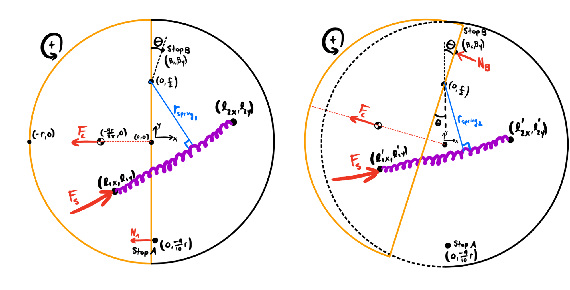
To achieve the required nonlinear functionality, my partner and I knew that we would need a nonlinear torque mechanism. We decided on a design centered around a spring, anchored to the base flywheel on one end and the protrusion mechanism on the other. In the starting position, the spring was pretensioned to keep the protrusion mechanism retracted until 1600 RPM. As the angular speed of the flywheel increased, the centrifugal “force” (yes, centrifugal force is not a true force, but was considered as such for the sake of making future analysis more intuitive) acting on the mechanism's center of mass also increased. Eventually, the moment caused by the centrifugal force would overcome the moment caused by the pretensioned spring force, leading the mechanism to spin outwards and extend by only one centimeter, limited by a stop post. Then, because the moment arm of the spring in the protruded position is much shorter, the flywheel would have to slow down to 1300 RPM in order for the spring moment to once again overcome the centrifugal moment, allowing the mechanism to retract once again. This design is visualized by the free body diagram that we created in the beginning of the design process, shown below:
To determine the precise dimensions, properties, and placements required for this design, complex trigonometry or vector operations such as cross products were necessary. The optimal spring post positions were impossible to analytically solve by hand, so I wrote three custom MATLAB scripts, which worked together to numerically calculate the best spring post positions. These scripts were center_of_mass.m, sim_moments.m, and find_best_params.m.
First, center_of_mass.m, as one might expect, calculated the mass of the flywheel’s protrusion mechanism and the location of its center of mass.
These values were then fed into sim_moments.m, which, when given the locations of the spring posts, calculated the sum of moments at both the pop-out and pop-in speeds. It did this through a lengthy process of vector operations and coordinate system conversions.
Finally, find_best_params.m simulated hundreds of thousands of possible spring post locations, used sim_moments.m to calculate the moments in each scenario, and finally determined which location would most accurately target pop-out and pop-in speeds of 1600 RPM and 1300 RPM, respectively.
The analytically optimal configuration was then visualized in run_one_config.m, which generated the following figure:
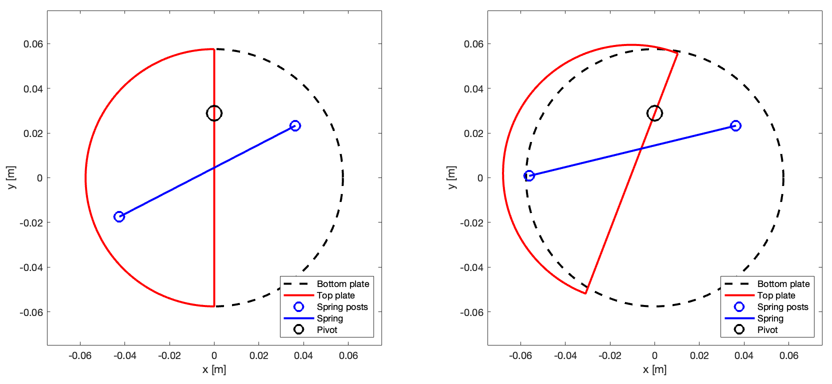
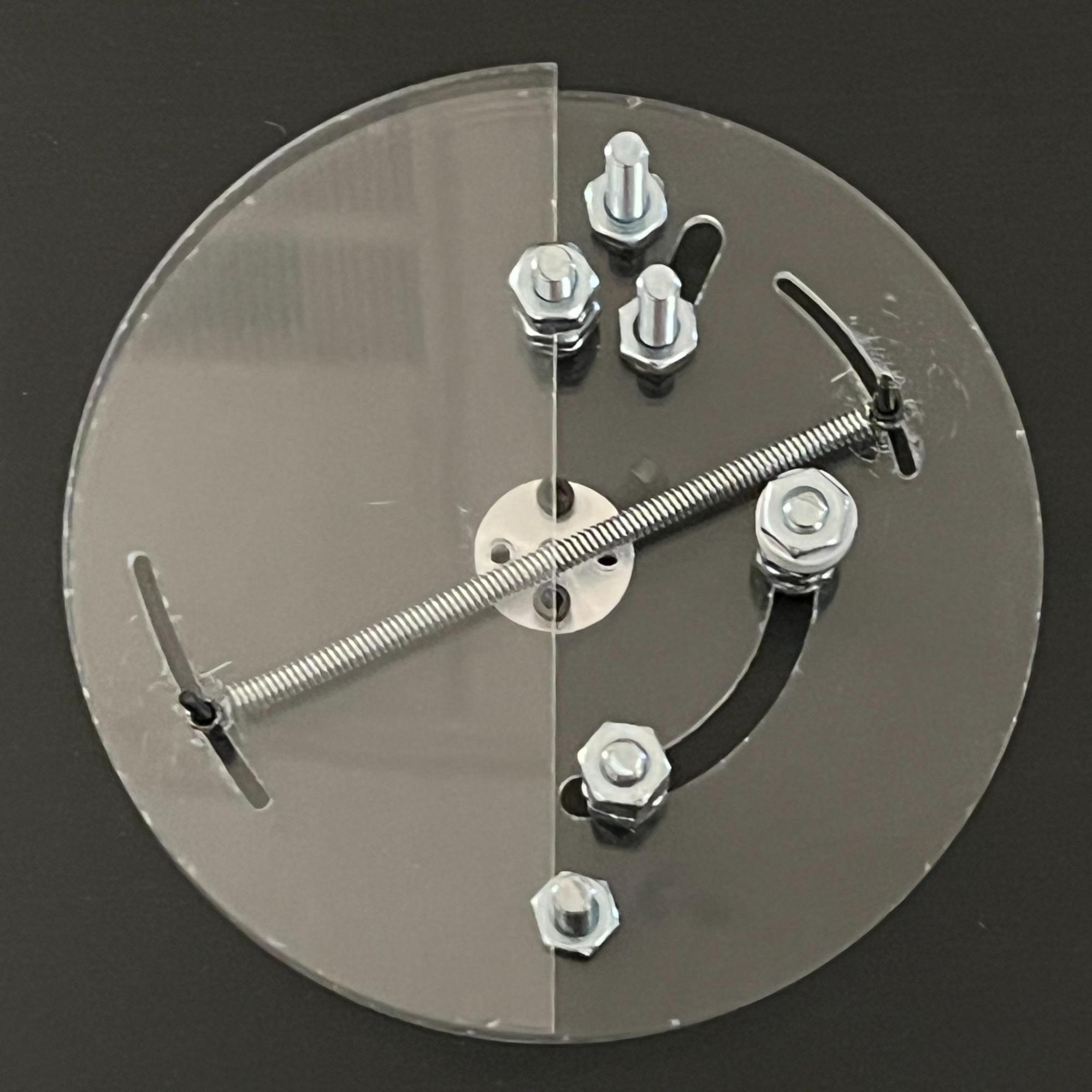
After using these scripts to identify and visualize the optimal design configuration, we used these exact specifications to create a detailed CAD model of the flywheel. This model was then imported into AutoCAD, where we used it to laser cut the acrylic flywheel pieces. After assembly with a spring and a few nuts and bolts, we had our first prototype:
As can be seen, we included two angular slots, centered about the theoretically optimal spring post locations. Because of certain assumptions made, such as no aerodynamic drag or bearing friction, there would be small inaccuracies within the MATLAB calculations. These angular slots would allow for fine-tuning adjustments to account for these inaccuracies.
However, after initial testing, it became apparent that the flywheel motor struggled to reach the target 1600 RPM due to extreme vibrations. This was caused by our design's lack of symmetry, which had the center of mass too far away from the motor’s axis. These vibrations limited the flywheel's speed, and more importantly, risked damaging our motor. We quickly recognized the need for counterweights to bring the center of mass closer to the motor's axis, mitigating the vibrations and ensuring smoother operation.
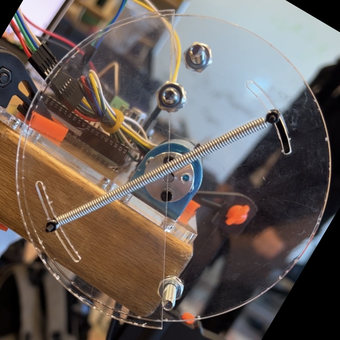
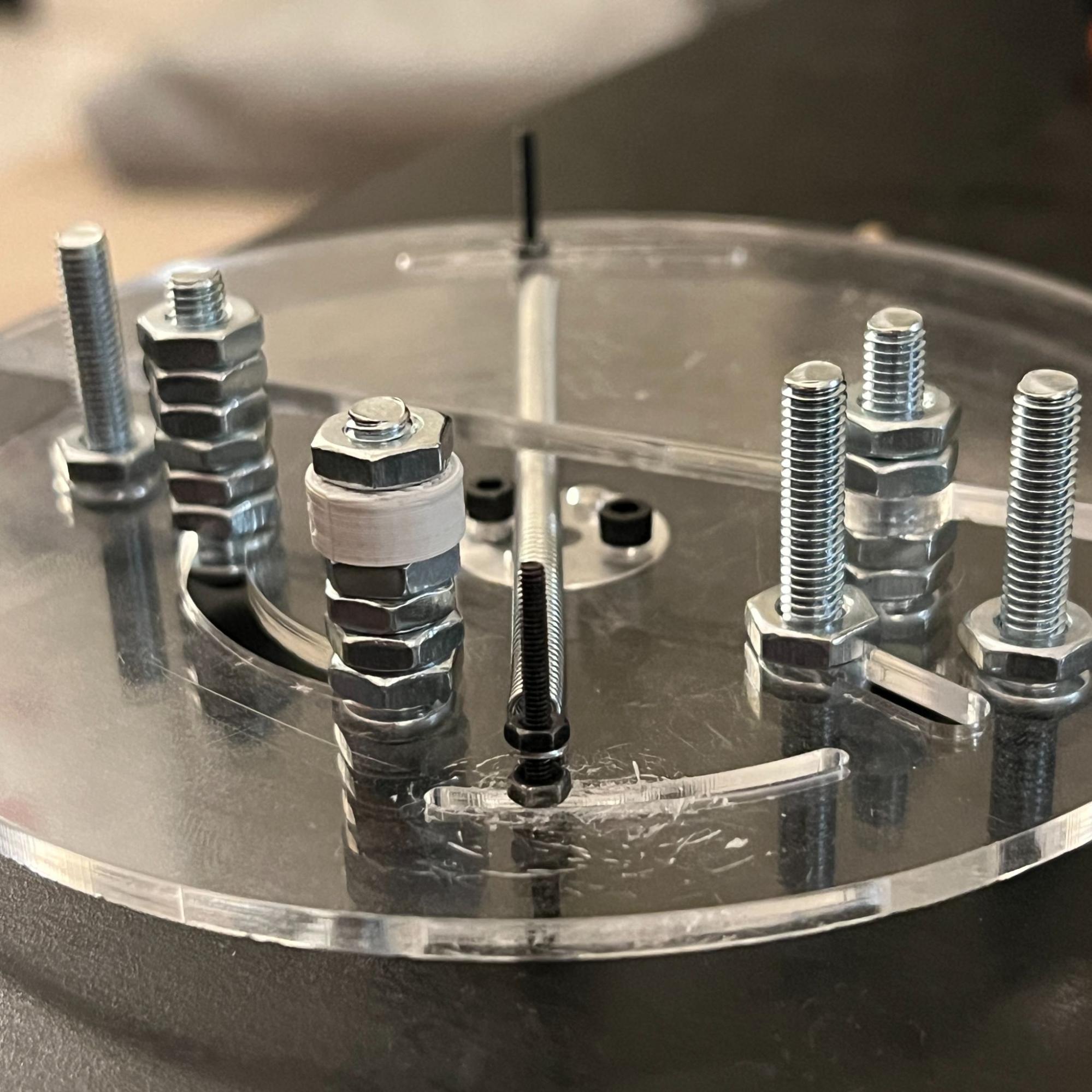
After modifying our design to include two small slots intended for counterweights, we quickly remanufactured our flywheel to get our second prototype. This prototype, fitted with the necessary counterweights (nuts and bolts) is pictured below:
Finally, we focused on fine-tuning the prototype’s performance. Although our initial spring post locations yielded promising results, we aimed to achieve pop-out and pop-in speeds even closer to 1600 RPM and 1300 RPM. To inform our fine-tuning process, I wrote another MATLAB script, find_best_posts.m. This script, when provided with the target pop-out and pop-in speeds, determined the optimal positions along the two adjustable spring post slots to theoretically reach these desired speeds. This was incredibly useful in the fine-tuning process and allowed us to offset the errors made in the theoretical model; for example, if the default spring posts, theoretically targeting 1600 RPM and 1300 RPM, yielded experimental pop-out and pop-in speeds of 1700 RPM and 1400 RPM, we would adjust the spring posts to positions that targeted a theoretical 1500 RPM and 1200 RPM to adjust for this, then continue iterating this process. This method allowed us to effectively fine-tune our design, bringing us closer to our desired speeds.
On this project’s day of evaluation, our flywheel demonstrated pop-out and pop-in speeds of 1577.2 RPM and 1324 RPM, respectively. A video of this is shown below:
These speeds represented only a 1.64% error from the target speeds of 1600 RPM and 1300 RPM. However, reflecting on the project, there are several aspects I would approach differently if I were to create a similar mechanism in the future:
- Reduce Flywheel Mass: In this project, the use of dense acrylic and heavy nuts and bolts necessitated a strong spring to offset the centrifugal force. It should be noted that we were provided a limited set of springs and materials to make our flywheel out of, so our choice of spring was limited. To improve the flywheel's consistency and stability, I would opt for a lighter-weight 3D printed PLA flywheel. This change would allow for the use of a less powerful and therefore less sensitive spring, while maintaining optimal performance.
- Higher Frequency Data Collection: Using a custom Arduino script to control the speed of the flywheel, while effective, had limitations in accurately maintaining specific speeds at high RPMs due to its sampling rate. In future iterations, I would explore using a higher frequency data collection method to increase the accuracy of speed control, which would subsequently improve the fine-tuning process.
- Radially Symmetric Design: The initial design's lack of symmetry required the addition of counterweights to offset the center of mass closer to the motor's axis. To eliminate the need for counterweights and achieve more consistent performance, I would focus on designing a radially symmetric flywheel which would ensure stability and minimize vibrations during operation.
Overall, I’m very happy with the success of this project and the experience that I gained in designing mechanical systems with the aid of precise computational analysis. All of the scripts that I wrote for this project are available below. If you have any questions about the design process, analytical methods, or any other aspect of this project, please feel free to contact me. Thanks for reading!
center_of_mass.m
function [mass, COM_vec] = center_of_mass(spring_post_pos,r)
%CENTER_OF_MASS calculates mass and center of mass of the top plate,
%including nuts, bolts, and holes.

%% Initialize known constants
r_b = 0.0024/2; % radius of bolt hole, in [m]
r_lb = 0.00561/2; % radius of 10-32 large bolt hole, in [m]
m_b = 0.029/100; % mass of an m2 bolt, in [kg]
m_n = 0.011/100; % mass of an m2 nut, in [kg]
d = 0.003; % thickness of top plate, in [m]
r_f = r; % radius of flywheel, in [m]
p_acrylic = 1180; % density of acrylic, in [kg/m^3]
slot_length = 30*r_b; % length of adjustable spring post slot, in [m]

%% Calculate point masses
m_plate = pi/2 * r_f^2 * d * p_acrylic; % mass of half circle plate
m_pivot = pi * p_acrylic * r_lb^2 * d; % change in mass due to pivot design
m_post = m_b + m_n - p_acrylic*d*(pi*r_b^2 + (2*r_b)*(slot_length-2*r_b)); % change in mass due to spring post and adjustable slot

%% Calculate/define location of masses
r_plate = [-4*r_f/(3*pi); 0];
r_pivot = [0; r_f/2]; % NOTE: this is a small assumption but should be fairly accurate
r_post = spring_post_pos(1:2);

%% Calculate mass and center of mass
mass = m_plate + m_pivot + m_post;
x_COM = (m_plate*r_plate(1) + m_pivot*r_pivot(1) + m_post*r_post(1))/mass;
y_COM = (m_plate*r_plate(2) + m_pivot*r_pivot(2) + m_post*r_post(2))/mass;
COM_vec = [x_COM; y_COM; 0];

end
sim_moments.m
function [moment1,moment2] = sim_moments(spring_angle,post_angle,xpretension,plotflag)
r = 0.115/2; %4.5 * 2.54 / 100; % radius of flywheel, [m]
r_b = 0.001; % radius of bolt hole, in [m]
RPM2rps = 1*2*pi/60;
w1 = 1600*RPM2rps;
w2 = 1300*RPM2rps;

% Spring properties (CHANGE THESE PARAMETERS)
sp.k = 1010.196429; % Spring constant in [N/m]
sp.xi = 0.0698 + 2*r_b; % Unstretched length of spring in [m]
sp.xpretension = xpretension; % Required additional pretension length in [m]
sp.angle = spring_angle; % Angle of spring in relation to pos x axis from fixed post in [deg]

%% Define positions 1 and 2 in each coordinate system
% Fixed Spring Post position
r_sf.r = 3*r/4; % Radius in relation to center
r_sf.angle = post_angle; % Angle in relation to positive x axis
r_sf.c = [r_sf.r*cosd(r_sf.angle); r_sf.r*sind(r_sf.angle); 0];
r_sf.p = T_c_p(r_sf.c,r);

% Top Plate Spring Post position
r_st.d1 = sp.xi + sp.xpretension; % Distance from fixed post at position 1
r_st.c1 = [r_sf.c(1) + r_st.d1*cosd(sp.angle); r_sf.c(2) + r_st.d1*sind(sp.angle); 0];
if r_st.c1(1) > 0 || norm(r_st.c1) > r
    moment1 = Inf;
    moment2 = Inf;
    return;
end
r_st.p1 = T_c_p(r_st.c1,r);
r_st.p2 = T_p1_p2(r_st.p1,r);
r_st.c2 = T_p_c(r_st.p2,r);

% Center of Mass position
[m, r_COM.c1] = center_of_mass(r_st.c1,r);
r_COM.p1 = T_c_p(r_COM.c1,r);
r_COM.p2 = T_p1_p2(r_COM.p1,r);
r_COM.c2 = T_p_c(r_COM.p2,r);

%% Define forces
% Centrifugal Force
F_cent.c1 = (m*w1^2*norm(r_COM.c1)) * r_COM.c1/norm(r_COM.c1);
F_cent.c2 = (m*w2^2*norm(r_COM.c2)) * r_COM.c2/norm(r_COM.c2);

% Spring force
F_spring.c1 = (sp.k*sp.xpretension) * (r_sf.c-r_st.c1)/norm(r_sf.c-r_st.c1);
F_spring.c2 = (sp.k*(norm(r_st.c2-r_sf.c) - sp.xi)) * (r_sf.c-r_st.c2)/norm(r_sf.c-r_st.c2);

%% Calculate and print moments

M.p1 = cross(r_COM.p1,F_cent.c1) + cross(r_st.p1,F_spring.c1);
M.p2 = cross(r_COM.p2,F_cent.c2) + cross(r_st.p2,F_spring.c2);
moment1 = M.p1(3);
moment2 = M.p2(3);

%% Transformation functions
function rp = T_c_p(rc,r)
% transformation from center coords to pivot coords
rp(1,:) = rc(1,:);
rp(2,:) = rc(2,:) - r/2;
rp(3,:) = 0;
end

function rc = T_p_c(rp,r)
% transformation from pivot coords to center coords
rc(1,:) = rp(1,:);
rc(2,:) = rp(2,:) + r/2;
rc(3,:) = 0;
end

function p2 = T_p1_p2(p1,~)
% rotational transformation about pivot
p1(3,:) = 1; th = -21;
p2 = [cosd(th) -sind(th) 0;
      sind(th) cosd(th) 0;
      0 0 1] * p1;
p2(3,:) = 0;
end
end
find_best_params.m
clear all; close all;

%% Define adjustable parameters
% Number of iterations for each variable
iterations = 300;
% Angle from the fixed spring post to the top plate spring post
springAngleRange = linspace(207.3,207.45,iterations);
% Angle from the center to the fixed spring post
postAngleRange = linspace(32.5,32.75,iterations);
% Pretension, in [m], applied to the spring at position 1 (starting
% position)
pretensionRange = linspace(0.0167,0.016795,1);

warningFlag = false;
minMoment = 10000;
springAngleAr = [];
moment1Ar = [];
moment2Ar = [];
tic;
for springAngle = springAngleRange
    pct_done = 100 * abs(springAngle-springAngleRange(1))/abs((springAngleRange(end)-springAngleRange(1)));
    fprintf('Loading... %2.f%%\n',pct_done);
    for postAngle = postAngleRange
        for pretension = pretensionRange
            [moment1, moment2] = sim_moments(springAngle,postAngle,pretension);
            if moment1 == Inf
                warningFlag = true;
            end
            springAngleAr = [springAngleAr springAngle];
            moment1Ar = [moment1Ar moment1];
            moment2Ar = [moment2Ar moment2];
            totalMoment = abs(moment1) + abs(moment2);

            if totalMoment < minMoment
                bestMoment1 = moment1;
                bestMoment2 = moment2;
                minMoment = totalMoment;
                bestSpringAngle = springAngle;
                bestPostAngle = postAngle;
                bestPretension = pretension;
            end
        end
    end
end

if warningFlag
    warning('One or more of the simulated spring posts is outside the flywheel. This is normal with large ranges.');
end

springAngleRes = diff(springAngleRange);
postAngleRes = diff(postAngleRange);
pretensionRes = diff(pretensionRange);
try
    springAngleRes = springAngleRes(1);
    postAngleRes = postAngleRes(1);
    pretensionRes = pretensionRes(1);
catch
    springAngleRes = [];
    postAngleRes = [];
    pretensionRes = [];
end

toc;
fprintf('\nBest Spring Angle: %.4f deg, resolution of %.6f deg\n',bestSpringAngle,springAngleRes);
fprintf('Best Post Angle: %.4f deg, resolution of %.6f deg\n',bestPostAngle,postAngleRes);
fprintf('Best Pretension: %.5f m, resolution of %.6f m\n\n',bestPretension,pretensionRes);
fprintf('At these parameters: M_1 = %.6f, M_2 = %.6f\n',bestMoment1,bestMoment2);
run_one_config.m
clear all; clc; close all;
r = 0.115/2; %4.5 * 2.54 / 100; % radius of flywheel, [m]
d_p = 0.01; % length of protrusion of flywheel, [m]
r_b = 0.001; % radius of bolt hole, in [m]
RPM2rps = 1*2*pi/60;
w1 = 1600*RPM2rps;
w2 = 1300*RPM2rps;
theta = -21;
plotflag = true;

% Spring properties (CHANGE THESE PARAMETERS)
sp.k = 1010.196429; % Spring constant in [N/m]
sp.xi = 0.0698 + 2*r_b; % Unstretched length of spring in [m]
sp.xpretension = 0.016795; % Required additional pretension length in [m]
sp.angle = 207.3566889632107; % Angle of spring in relation to pos x axis from fixed post in [deg]

%% Define positions 1 and 2 in each coordinate system
% Fixed Spring Post position
r_sf.r = 3*r/4; % Radius in relation to center
r_sf.angle = 32.668896321070235; % Angle in relation to positive x axis
r_sf.c = [r_sf.r*cosd(r_sf.angle); r_sf.r*sind(r_sf.angle); 0];
r_sf.p = T_c_p(r_sf.c,r);

% Protrusion position
r_pro.c1 = [-r;0;0];
r_pro.p1 = T_c_p(r_pro.c1,r);
r_pro.p2 = T_p1_p2(r_pro.p1,theta);
r_pro.c2 = T_p_c(r_pro.p2,r);

% Top Plate Spring Post position
r_st.d1 = sp.xi + sp.xpretension; % Distance from fixed post at position 1
r_st.c1 = [r_sf.c(1) + r_st.d1*cosd(sp.angle); r_sf.c(2) + r_st.d1*sind(sp.angle); 0];
r_st.p1 = T_c_p(r_st.c1,r);
r_st.p2 = T_p1_p2(r_st.p1,theta);
r_st.c2 = T_p_c(r_st.p2,r);

% Center of Mass position
[m, r_COM.c1] = center_of_mass(r_st.c1,r);
r_COM.p1 = T_c_p(r_COM.c1,r);
r_COM.p2 = T_p1_p2(r_COM.p1,theta);
r_COM.c2 = T_p_c(r_COM.p2,r);

%% Define forces
% Centrifugal Force
F_cent.c1 = (m*w1^2*norm(r_COM.c1)) * r_COM.c1/norm(r_COM.c1);
F_cent.c2 = (m*w2^2*norm(r_COM.c2)) * r_COM.c2/norm(r_COM.c2);

% Spring force
F_spring.c1 = (sp.k*sp.xpretension) * (r_sf.c-r_st.c1)/norm(r_sf.c-r_st.c1);
F_spring.c2 = (sp.k*(norm(r_st.c2-r_sf.c) - sp.xi)) * (r_sf.c-r_st.c2)/norm(r_sf.c-r_st.c2);

%% Calculate and print moments
M.p1 = -norm(cross(r_COM.p1,F_cent.c1)) + norm(cross(r_st.p1,F_spring.c1));
M.p2 = -norm(cross(r_COM.p2,F_cent.c2)) + norm(cross(r_st.p2,F_spring.c2));

fprintf('Sum of moments about pivot at position 1: %.4f N*m\n',M.p1);
fprintf('Sum of moments about pivot at position 2: %.4f N*m\n',M.p2);

%% Plot diagram of position 1
if plotflag == true
    subplot(1,2,1);
    hold on; axis equal; box on;
    xlim([-1.3*r 1.3*r]); ylim([-1.3*r 1.3*r]);

    % Plot base flywheel
    viscircles([0 0],r,'Color','black','LineStyle','--');
    plot(10*r,10*r,'k--','LineWidth',2); % Plot off screen point for legend

    % Plot top plate
    % Half circle arc
    t = linspace(pi/2,3*pi/2,100);
    x_tp1 = r*cos(t);
    y_tp1 = r*sin(t);
    % Center line
    x_tp1 = [x_tp1 0 0];
    y_tp1 = [y_tp1 -r r];
    plot(x_tp1,y_tp1,'r-','LineWidth',2);

    % Plot spring posts and spring
    plot([r_st.c1(1) r_sf.c(1)],[r_st.c1(2) r_sf.c(2)],'bo','MarkerSize',10,'LineWidth',2);
    line([r_st.c1(1) r_sf.c(1)],[r_st.c1(2) r_sf.c(2)],'LineWidth',2,'Color','b');

    % Plot pivot
    plot(0,r/2,'ko','LineWidth',2,'MarkerSize',15);

    % Format plot
    xlabel('x [m]'); ylabel('y [m]'); %title('Position 1');
    legend('Bottom plate','Top plate','Spring posts','Spring','Pivot','Location','southeast');

    %% Plot diagram of position 2
    subplot(1,2,2);
    hold on; axis equal; box on;
    xlim([-1.3*r 1.3*r]); ylim([-1.3*r 1.3*r]);

    % Plot base flywheel
    viscircles([0 0],r,'Color','black','LineStyle','--');
    plot(10*r,10*r,'k--','LineWidth',2); % Plot off screen point for legend

    % Plot top plate
    % Half circle arc
    t = linspace(pi/2,3*pi/2,100);
    x_tp2 = r*cos(t);
    y_tp2 = r*sin(t);
    % Center line
    x_tp2 = [x_tp2 0 0];
    y_tp2 = [y_tp2 -r r];
    % Rotate about pivot
    tp2_points = [x_tp2;
                  y_tp2;
                  zeros(1,length(x_tp2))];
    tp2_points = T_c_p(tp2_points,r);
    tp2_points = T_p1_p2(tp2_points,theta);
    tp2_points = T_p_c(tp2_points,r);
    x_tp2 = tp2_points(1,:);
    y_tp2 = tp2_points(2,:);
    plot(x_tp2,y_tp2,'r-','LineWidth',2);

    % While we're here, calculate actual protrusion distance
    distance_tp2 = sqrt(x_tp2.^2 + y_tp2.^2);
    actual_protrusion = 100*(max(distance_tp2) - r); % In cm
    fprintf('Protrusion distance: %.2f cm\n',actual_protrusion);

    % Plot spring posts and spring
    plot([r_st.c2(1) r_sf.c(1)],[r_st.c2(2) r_sf.c(2)],'bo','MarkerSize',10,'LineWidth',2);
    line([r_st.c2(1) r_sf.c(1)],[r_st.c2(2) r_sf.c(2)],'LineWidth',2,'Color','b');

    % Plot pivot
    plot(0,r/2,'ko','LineWidth',2,'MarkerSize',15);

    % Format plot
    xlabel('x [m]'); ylabel('y [m]'); %title('Position 2');
    legend('Bottom plate','Top plate','Spring posts','Spring','Pivot','Location','southeast');
    set(gcf,'Position',[100 400 1000 500])
end
%% Transformation functions
function rp = T_c_p(rc,r)
% transformation from center coords to pivot coords
rp(1,:) = rc(1,:);
rp(2,:) = rc(2,:) - r/2;
rp(3,:) = 0;
end

function rc = T_p_c(rp,r)
% transformation from pivot coords to center coords
rc(1,:) = rp(1,:);
rc(2,:) = rp(2,:) + r/2;
rc(3,:) = 0;
end

function p2 = T_p1_p2(p1,theta)
% rotational transformation about pivot
p1(3,:) = 1; th = theta;
p2 = [cosd(th) -sind(th) 0;
      sind(th) cosd(th) 0;
      0 0 1] * p1;
p2(3,:) = 0;
end
find_best_posts.m
clear all; close all; clc;

minRPM = 1000; maxRPM = 2000; n_RPM = 1000;
n_posts = 50;
targetw1 = 1680; targetw2 = 1350;
tic;

% Original Bottom Spring Post position
bot0.pos = [0.0363027946392283; 0.0232781598581593; 0];
bot0.original_angle = atan2d(bot0.pos(2),bot0.pos(1));
bot0.d = norm(bot0.pos);
bot0.angle_range = 18.17941602; % deg
bot0.angle_ar = linspace(bot0.original_angle - bot0.angle_range, ...
                          bot0.original_angle + bot0.angle_range, ...
                          n_posts);

% Original Top Plate Spring Post position
top0.pos = [-0.0423840068559378; -0.0174337707698561; 0];
top0.original_angle = atan2d(top0.pos(2) - bot0.pos(2), top0.pos(1) - bot0.pos(1));
top0.d = norm(bot0.pos - top0.pos); %0.088595;
top0.angle_range = 15.30325048; % deg
top0.angle_ar = linspace(top0.original_angle - top0.angle_range, ...
                        top0.original_angle + top0.angle_range, ...
                        n_posts);

w1_ar = zeros(n_posts);
w2_ar = zeros(n_posts);
m1_ar = zeros(n_posts);
m2_ar = zeros(n_posts);
for botIndex = 1:n_posts
    bot.angle = bot0.angle_ar(botIndex);
    bot.pos = [bot0.d*cosd(bot.angle);
               bot0.d*sind(bot.angle);
               0];
    for topIndex = 1:n_posts
        top.angle = top0.angle_ar(topIndex);
        top.pos = [bot0.pos(1) + top0.d*cosd(top.angle);
                   bot0.pos(2) + top0.d*sind(top.angle);
                   0];
%         figure(1); hold off;
%         plot(top.pos(1),top.pos(2),'ro'); hold on;
%         plot(bot.pos(1),bot.pos(2),'ro');
        ylim([-0.1 0.1]); xlim([-0.1,0.1]);
        [popOut, popIn, popOutMoment, popInMoment] = findspeeds(bot.pos,top.pos,minRPM,maxRPM,n_RPM);
        w1_ar(botIndex,topIndex) = popOut;
        w2_ar(botIndex,topIndex) = popIn;
        m1_ar(botIndex,topIndex) = popOutMoment;
        m2_ar(botIndex,topIndex) = popInMoment;
    end
end

%% Find best setup

error_ar = zeros(n_posts,n_posts);
for botIndex = 1:n_posts
    for topIndex = 1:n_posts
        w1 = w1_ar(botIndex,topIndex);
        w2 = w2_ar(botIndex,topIndex);
        error_ar(botIndex,topIndex) = abs(w1-targetw1) + abs(w2-targetw2);
    end
end


bestError = min(error_ar,[],'all');
[bestBotIndex, bestTopIndex] = find(error_ar == bestError);
bestw1 = w1_ar(bestBotIndex,bestTopIndex);
bestw2 = w2_ar(bestBotIndex,bestTopIndex);
bestm1 = m1_ar(bestBotIndex,bestTopIndex);
bestm2 = m2_ar(bestBotIndex,bestTopIndex);
bestBotAngle = bot0.angle_ar(bestBotIndex);
bestTopAngle = top0.angle_ar(bestTopIndex);
botAnglePct = 100*(bestBotAngle - bot0.original_angle)/bot0.angle_range;
topAnglePct = 100*(bestTopAngle - top0.original_angle)/top0.angle_range;

toc;
fprintf('To achieve %.f RPM pop-out and %.f RPM pop-in, adjust:\n',bestw1,bestw2);
fprintf('\tthe bottom plate spring post to %.1f%%\n',botAnglePct);
fprintf('\tthe top plate spring post to %.1f%%\n',topAnglePct);

fprintf('At these speeds, the moments are:\n');
fprintf('\tM_1 = %.4f N*m\n',bestm1);
fprintf('\tM_2 = %.4f N*m\n',bestm2);